Slewing Ring Bearings & Drives
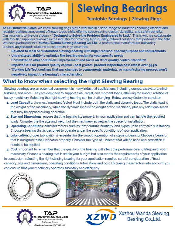
We know slewing rings play a vital role in a wide-range of industries enabling efficient and reliable rotational movement of heavy loads while offering space-saving design, durability, and safety benefits. Our mission is to live our slogan – “Designed to Solve the Problem, Engineered to Last.” This is why we collaborate with top-tier suppliers renown in the industry for providing high-quality, tailored solutions that perform in the field.
Tour one of our Manufacturers

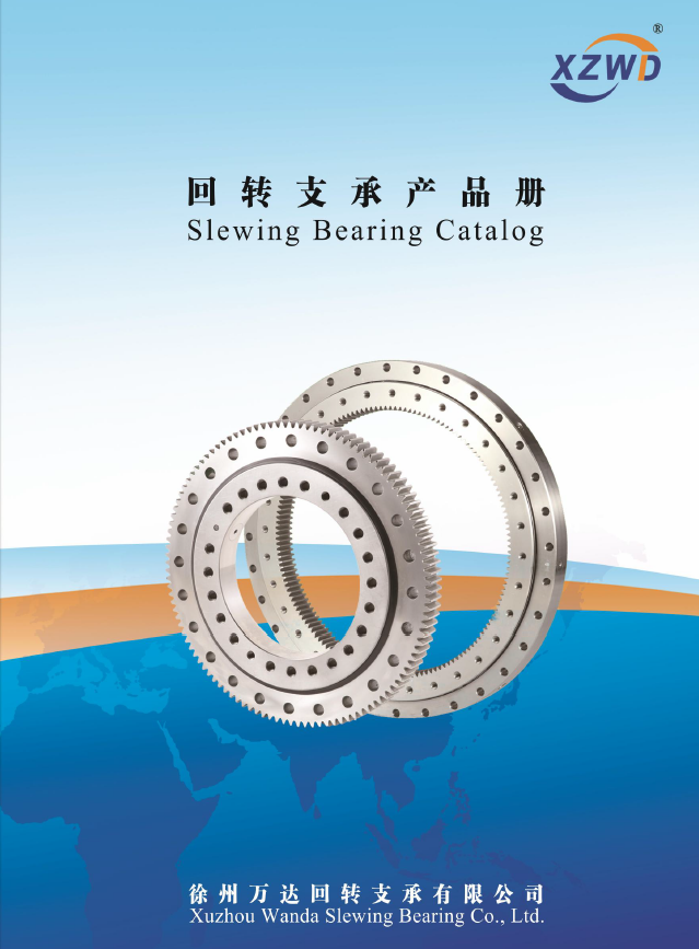
A slewing ring is a rotational bearing that typically supports a heavy but slow-turning or slow-oscillating load, such as a conventional crane, a swing yarder, or the wind-facing platform of a horizontal-axis windmill. Compared to other rolling-element bearings, slewing rings are thin and lightweight but may range in size to over 1 meter. Slewing rings are often made with gear teeth either on the inner or outer race. These gear teeth are used to drive the platform relative to the base. Our slewing rings are designed to handle extreme elements and rigorous applications.
The slewing ring is unique in that it can withstand large loads such as axial, radial, or tilting moment load. When selecting a slewing ring it is important that all specifications meet the load calculation data. Slewing rings contain an outer ring, inner ring, rolling body, and seals. Our slewing ring material is generally made up of high alloy-structural steels, such as 42CrMo 50Mn. A slewing ring can withstand normal temperatures of -30℃ to +70℃ but can be specially formulated for even more extreme temperatures.
Today’s modern cranes mainly use large diameter slewing rings for the core rotating of the main structure. Slewing rings are comprised of both inner and outer races and typically have an integral gear. Typical slewing rings range in size from approximately 9” to 5m in diameter. A slewing rings rotation is achieved by the balls contained within the races. There are numerous advantages for the slewing ring configuration when compared to the king post.

When a crane uses a slewing ring, you should pay attention to the following tips:
- Visually inspect the bolts each day on the slewing ring or at least once a week.
- After the slewing ring has incurred 100 working hours, check whether the bolts are loose. You can then wait till the 300th working hour, while also doing additional checks every additional 500 working hours. You may shorten the inspection interval in hazardous working conditions. If the bolt is loose during the inspection, please stop your process immediately and contact the local after-sales service department. The crane manufacturer or professional technician will determine proper action.
- All slewing rings ae filled with lithium-based grease before installation.
- When replacing the bolts, wipe the bolts clean and apply the thread fastening compound and tighten them. You may check the fastening bolts regularly to avoid fatigue damage to the bolts.
Production Description
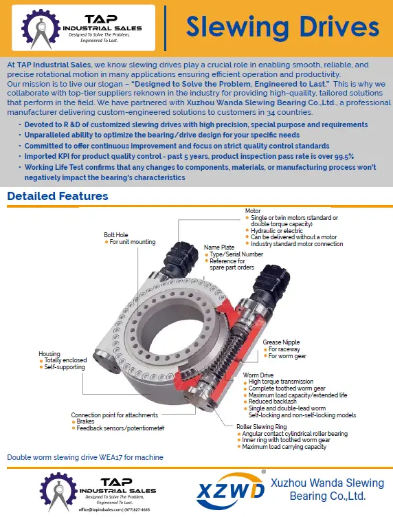
Slewing drives come in all different designs and sizes and can be used on machinery such as wind turbines, military equipment, digger derricks, fog cars, medical equipment, forestry equipment, and industrial positioners. One of the most popular designs incorporates a fully enclosed housing which includes all drive components, such as the double enveloping worm gear, planetary gearing, and slewing ring. This can be advantageous by keeping these parts away from the elements as well as dirt and debris that may enter a non-enclosed unit. The Enclosed Drive is mounted inside which can help reduce workplace injuries when working in proximity.
Hydraulic slew drive devices are composed of a hydraulic motor, reducer, gear end, and other components, which can all help improve product efficiency. One of the biggest advantages of the hydraulic slew drive device is its ease of installation as well as maintenance. What exactly is a hydraulic slewing drive device?
1.Concept of hydraulic slew drive device
2. How to distinguish the model of hydraulic slewing drive device?
3. Selection of hydraulic slew drive device

1. Concept of hydraulic slew drive device

Hydraulic slew drive devices are composed of a hydraulic motor, brake, reducer, valve group and gear end structure in a modular design. It is transmitted to the gearbox through the hydraulic motor which increases torque and reduces speed. Due to the high integration of hydraulic slew drive device, the user does not have to purchase or process each part of the rotary device. This helps reduce the preparation process at the beginning of production, which in turn greatly improves labor productivity.
2. How to distinguish the model of hydraulic slewing drive device?
Hydraulic actuators are one of the five basic components of a hydraulic system. Hydraulic actuator refers to the device that converts hydraulic energy into mechanical energy and captures linear motion and output force or torque. Hydraulic actuators can be divided into hydraulic motors and hydraulic cylinders.
3.Selection of hydraulic slew drive device
Hydraulic Slew Drives are allowed to work under high back pressure. In continuous operation, the back pressure is 10MPa. The maximum allowable pressure of shell is 0.3MPa. If you have special requirements, please contact the manufacturer. Hydraulic oil: it is recommended to use high quality, anti-foam and anti-oxidation mineral based hydraulic oil. The ideal working oil temperature is 30 -50 C, and oil temperatures of -20 to 80 C. When the oil temperature is below 10 C, low pour point hydraulic oil must be used. The viscosity of the hydraulic oil is 40~60 centigrade, and the allowable rate is 5~300 centigrade. The filtering accuracy of the liquid oil is recommended as 25um or higher filtration precision. The hydraulic transmission device can rotate in both directions.
Oil drainpipe positioning: hydraulic slewing drive devices can be installed in any direction: In order to ensure proper lubrication, it is necessary to fill the unit with hydraulic oil before operation. The Oil inlet and outlet direction of the distributor is allowed to rotate at 72 ° interval according to the contour installation connection position. However, the sealing function of a plain O-ring cannot be damaged when loosening or rotating the screw.
Hydraulic slew drive devices can be used in any situation that requires full circle rotation and speed change requirements. It has the advantages of simple structure, convenient manufacturing, maintenance, and strong practicability. It is widely used in aerial vehicles, photovoltaic power generators, wind power generators, and engineering machinery grapples. If you want to know more about hydraulic slew drive devices, please contact TAP Industrial Sales.

Installation preparation
1.1 Unpacking slewing rings
Carefully unpack the slewing ring. Care must be taken not to cut and damage the integral seals.
1.2 Slewing ring mounting structure requirement
The supporting surfaces must have a flat machined surface (usually machine roughness 6.3) and be rigid enough to eliminate torsional buckling under load that would affect the smooth operation of the slewing ring.
The thickness if the supporting plates should be no less than that indicated below-which is offered as a rough approximation only.
| Raceway Dia(mm) | 500 | 750 | 1000 | 1250 | 1500 | 2000 | 2500 | 3000 |
| Min Suport Thickness(mm) |
25 | 30 | 35 | 40 | 50 | 60 | 70 | 80 |
The width of the supporting surface must be at least equal to the width of the ring it supports.
Permissible flatness deviation and deflections in supporting structure
In oRder for the bearing to slew smoothly, the mounting structure should be stress-relieved after welding procedure. The maximum permissible out-of-flatness, including slope and axial deflections is detailed in the respective tables.
The permissible deviations listed in Table 1 for the different design types are indicative values.
Regarding the slope of the machined surfaces, the figures shown in the table refer to a support width of 100mm. Another important factor is to ensure that the maximum value is reached only once per 180°sector.
To avoid larger deviations and occurrence of peaks in smaller sectors, any deviations in the range of 0°- 90°- 180°must only rise or fall gradually.
As in the case of out-of-flatness, any deflections in the supporting structure must not be allowed to lead to localized buckling which might cause tight spots in the raceways. This could easily lead to over-loads. For this reason, the same conditions as for the out-of flatness will apply.
For the maximum permissible deflections in Table 2, the permissible slope may be twice the value “P” in Table 1 (Reference width 100mm)
The maximum permissible axial deflections ”V” shown in Table 2 apply to all bearing types and are indicated as a function of the track diameter of the bearing.
Table 1 - Permissible out-of-flatness including slope “P” of the machined support surface
| Track Diameter | Out of flatness including slope per support surface “P” in mm | ||
| DL(mm) | Single-row ball Four point contact ball bearings | Double-row ball Eight point contact ball bearings | Roller bearing slewing rings |
| To 1000 | 0.15 | 0.20 | 0.10 |
| To 1500 | 0.19 | 0.25 | 0.12 |
| To 2000 | 0.22 | 0.30 | 0.15 |
| To 2500 | 0.25 | 0.35 | 0.17 |
| To 4000 | 0.30 | 0.40 | 0.20 |
| 4000~6000 | 0.40 | 0.50 | 0.30 |
| >6000~8000 | 0.50 | 0.60 | 0.40 |
Table 2 - Maximum permissible axial deflections for contact surfaces at maximum operating load
| Track Diameter in mm DL | To 1000 | To 1500 | To 2000 | To 2500 | To 3000 | To 3500 | To 4000 | To 5000 | To 5500 | To 6000 |
| Max. axial deflections in mm V | 0.6 | 0.8 | 1.0 | 1.3 | 1.6 | 2.0 | 2.5 | 3.0 | 3.6 | 4.2 |
Besides, the inner and outer ring of a slewing ring must rest fully on the supporting structure surface.
1.3 Mounting elements selection:
Choose bolts of recommended grade, quality class 10.9(metric) or SAE Grade 8 bolts. Don’t use a fully threaded bolt. Grade 12.9 bolts are used in very rare circumstances.
Only use treated hardened flat washers.
Use of elastic washers is absolutely prohibited. Do not reuse bolts, nuts and washers.
Installation of slewing ring
2.1 Hardness gap on slewing rings
The hardness gap occurs in the process of raceway inductive hardening and is located between the end and the beginning of the hardening. These areas must be placed in the area of least load: ideally at zero load when installing slewing ring.
The position of the hardness gap on each of the slewing ring can be told as follows:
| Slewing ring | Internal geared type | External geared type | Gearless type |
| Inner ring | S marking | Filler plug | S marking or filler plug |
| Outer ring | Filler plug | S marking | S marking or filler plug |
2.2 Fastening of slewing ring
Before fastening, use a feeler gauge to check whether the surface of the slewing ring is completely supported by the mounting structure. If this is not the case, the support surface of the mounting structure must be reworked.
Install all fasteners tighten lightly. Then tighten to specified value using a properly calibrated torque wrench; hydraulic devices are advisable. Follow the sequence pattern of the sketch below:
Before fastening, the mounting bolts should be coated slightly with oil. When tightening the whole bolt circle, ensure a uniform tightening torque.The recommend bolt tightening torque values are listed in the table below:
| Bolt Thread Size | Bore dia(mm) DIN/ISO 273 |
Tightening Torque at μ=0.14 Nm | |
| Bolt Class 8.8 | Bolt Class 10.9 | ||
| M12 | 14 | 79 | 117 |
| M14 | 16 | 126 | 184 |
| M16 | 17.5 | 193 | 279 |
| M18 | 20 | 270 | 387 |
| M20 | 22 | 387 | 558 |
| M24 | 26 | 666 | 954 |
| M27 | 30 | 990 | 1395 |
| M30 | 33 | 1350 | 1890 |
| UNC | Grade 5 | Grade 8 | |
| UNC 5/8”-11 | 18 | 180 | 260 |
| UNC 3/4”-10 | 21 | 320 | 460 |
| UNC 7/8”-9 | 25 | 520 | 730 |
| UNC 1”-8 | 27.5 | 770 | 1100 |
| UNC 1 1/8”-7 | 32 | 970 | 1560 |
| UNC 1 1/4”-7 | 35 | 1370 | 2190 |
| UNF | Grade 5 | Grade 8 | |
| UNF 5/8”-18 | 18 | 210 | 290 |
| UNF 3/4”-16 | 21 | 360 | 510 |
| UNF 7/8”-14 | 25 | 580 | 820 |
| UNF 1”-12 | 27.5 | 860 | 1210 |
| UNF 1 1/8”-12 | 32 | 1100 | 1760 |
| UNF 1 1/4”-12 | 35 | 1520 | 2440 |
The slewing ring should be rotated during tightening process as this will indicate the development of any tight spots, the cause of which must be investigated.
The bolt torque should be checked before machine is finally operated to check for any loss of pre-load due to the structure settling.
2.3 Pinion installation
The pinion should be located approximately at 90°of the major loading axis. Adjust the driving pinion to maximum eccentric point of the gear ring, usually with green or red paint coving 2 to 3 teeth. The backlash of the slewing ring gear and pinion must be within the limits of the calculated values or minimum at 0.05 x module. When several pinions are used, each one must be adjusted to the same conditions. During test, make sure good alignment of the pinion and of the slewing ring axes permits a satisfactory contact across all gear width. Before running, lubricate the slewing ring gear and pinion gear.
2.4 Running test
After final tightening of all fasteners:
Rotate the ring for at least 3 turns. Recheck the backlash value on the gear mesh over one full revolution. Measure the total deflection under a known load. The checked point should be marked. It is advisable to register these values in a maintenance logbook specific to the machine.
Deflection measurement under load mounted slewing ring
Operating process:
Place a measuring device between the two rings as closes as possible to the raceway on the main load axis: precision grade 0.1mm minimum. Calibrate to zero under a known load. Apply a measured load. Read the deflection value at the point considered. Repeat this measurement in the previously marked points. Take into account the deflection of the support structure and the fasteners elongation corresponding to the instrument position.
a: Axial Load (kN)
Fr: Radial Load (kN)
Me: Tilting Moment (kNm)
Q: Load to be lifted (kN)
A: Lifting Arm Weight (kN)
B: Balance Arm Weight (kN)
G: Stabilizing Load (kN)
W: Wind Load (kN)
lmax: Lifting Weight Length (max) (m)
a: Lifting Arm Center of Gravity Length (m)
b: Balance Arm Center of Gravity Length (m)
g: Balance Arm Length (m)
r: Wind Effect Distance with DTD (m)
Fa= Q + A + B + G
Me= (Q.lmax) + (A.a) – (G.g) – (B.b)
25 % Test Load Added:
Fa= (1,25.Q) + A + B + G
Me= (1,25.Q.lmax) + (A.a) – (G.g) – (B.b)
Wind Effect Added:
Fa= Q + A + B + G
Me= (Q.lmax) + (A.a) + (W.r) – (G.g) – (B.b)

You can easily calculate the axial loads and tilting moments on the Slewing Rings using the above equations. It is suggested that you use the maximum load and maximum distance values in your calculations. You can include additional test load and wind effect if you wish.
SAFETY FACTOR (f):
Loads should be multiplied with the safety factor suitable to the application area prior to gear selection after calculations are completed.
APPLICATION AREA SAFETY FACTOR (f)
Tower Cranes 1.25
Mobile Cranes 1.50
Harbor Cranes 1.25
Excavators 1.70
Concrete Pumps 1.50
Vehicle Mounted Platforms 1.35
Solar Energy Systems 1.25
Wind Energy Systems 2.00
Roller Systems 2.00
Industrial Designs 1.25
Radar Systems 1.10
Water Filtration Systems 1.25
industry applications


